Currently, there is extensive research on the mechanical parts of electric compressors, but there is relatively little research on the design and control of the compressor controller. This article analyzes and studies the control principles, software protection strategies, and vehicle interaction aspects of e-compressors, providing some reference for the design, development, and after-sales maintenance of
EV electric compressors.
1 Overview of Control Principle Design
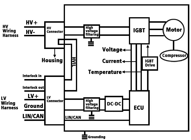
The typical control principle of an electric compressor controller is shown in Figure 1. The hardware part of the controller can be divided into the high-voltage power supply part, low-voltage control part, and high voltage interlock loop. When the compressor receives a low-voltage control signal, the IGBT turns on the high-voltage power supply, driving the motor to operate the compressor.
Figure 1. Electric compressor control schematic diagram
1.1 High-Voltage Power Supply Part
The HV power supply part includes high-voltage connectors, high-voltage filter circuits, and IGBTs. The high-voltage connectors connect to the vehicle's wiring harness, and the connector base is made of metal, conducted to the compressor housing through bolts. If there is a leakage at the connector, the current can be conducted through the compressor housing to the vehicle, and then to the ground.
The high-voltage filter circuit usually consists of multiple filter capacitors in parallel. The main purposes are twofold: first, to filter out abnormal fluctuations in the bus voltage to ensure that the voltage supplied to the compressor is stable, preventing large voltage fluctuations from damaging the compressor; second, to absorb the ripple voltage generated by the compressor due to power changes, preventing the ripple generated by the compressor from affecting the vehicle and other high-voltage components.
The IGBT is a crucial component in the AC controller. Generally, an
electric automotive ac compressor consists of six IGBTs, which control the high-voltage circuit by turning the IGBTs on and off, driving the motor compressor to work. Because the IGBT will conduct high voltage and frequently switch, its working environment is the harshest in the entire controller. Common IGBT failure modes include overcurrent, overvoltage, and overheating. To ensure that the IGBT works within an appropriate temperature range, many protection logics are usually added to the electric compressor controller.
1.2 Low-Voltage Control Part
The low-voltage control part includes low-voltage connectors, filter circuits, DC-DC converters, LIN/CAN communication circuits, sampling circuits, and the ECU. The low-voltage connectors connect to the wiring harness, providing low-voltage power and LIN/CAN signal communication for the compressor controller.
The filter circuit ensures the stability of the low-voltage input. The DC-DC converter converts 12V power to different voltages to supply power to different devices, such as the IGBT driver circuit, which generally requires a 15V regulated power supply, and the sampling circuit, which generally requires a 3.5V regulated power supply. LIN/CAN communication is the channel for interaction between the compressor and the vehicle, allowing the vehicle to send various commands to the compressor and the compressor to feedback its actual status to the vehicle. The sampling circuit detects the working voltage, current, temperature of the compressor, and hardware protection circuits.
The ECU is the core of signal interaction and transmission in the electric compressor controller. It receives LIN/CAN signals from the vehicle, simultaneously collects its own voltage, current, temperature, and status from various sampling circuits to determine whether the compressor meets the startup conditions. If conditions are met, the ECU sends a startup signal to the IGBT driver chip, driving the IGBT to turn on and off to start the compressor motor. The ECU continuously monitors the working status of all components, and if there is an abnormality, it immediately stops the compressor and feeds the fault mode back to the vehicle.
The purpose of the HV interlock circuit is to prevent personal safety issues caused by leakage due to the improper or poor connection of the electric compressor connectors. The principle is to ensure the normal operation of all high and low voltage circuits through a low voltage circuit. Only when all connectors are properly connected can the high-voltage components work normally. If the interlock circuit current exceeds the normal value, the vehicle will report an interlock circuit fault, and the high voltage cannot be activated.
2 Software Protection Strategies
Based on common failure modes of
HV compressors, protection strategies are designed to protect the compressor from further damage during abnormal operation by timely reducing power or shutting down. Protection strategies include LIN/CAN communication protection, temperature protection, overcurrent protection, overvoltage protection, and low-temperature preheating.
2.1 LIN/CAN Communication Protection
LIN/CAN communication protection refers to stopping the compressor immediately when communication errors like bit errors, PID errors, no response errors, frame errors, or physical bus errors occur for a certain period. The compressor resumes normal operation once communication is restored.
2.2 Over-Temperature Protection
Over-temperature protection involves stopping the compressor when the IGBT temperature is too high or too low (exceeding the set temperature range). The compressor resumes operation after the temperature returns to the set range and the stop time exceeds the set value. This protection prevents IGBT damage from operating outside its temperature range.
To avoid the inability to detect IGBT temperature due to sensor failure, generally, two temperature sensors are arranged inside the controller. The ECU uses the higher value from the sensors to determine the temperature, and if the absolute value difference between the two sensors exceeds the set value, it reports a temperature sensor fault.
2.3 Over-current Protection
Overcurrent protection aims to prevent damage to internal electrical components due to overcurrent. It includes bus current protection and phase current protection.
Bus current protection limits the input current to a certain value, and when exceeded, the compressor stops. Phase current protection prevents IGBT damage since phase current correlates directly with the compressor load. Overcurrent protection also links with temperature protection to reduce phase current limits as the IGBT temperature increases, preventing IGBT damage from operating under high current and temperature conditions.
2.4 Overvoltage Protection
Overvoltage protection limits compressor speed or stops the compressor when the voltage exceeds the operating range. It includes high-voltage protection and low-voltage protection, further divided into 12V power protection and 15V drive voltage protection.
High-voltage protection prevents internal component damage from high input voltage and limits power or stops the compressor under low input voltage. Due to instability in the market, high-voltage protection combines software and hardware protections to detect ms-level and us-level voltage spikes, respectively. To prevent high-voltage sensor failure, two sensors are arranged inside the controller, comparing values regularly, and stopping the compressor if the difference exceeds the set value.
Upon detecting overvoltage, the compressor operates at limited power, reducing speed until the voltage returns to normal. Low-voltage protection includes 12V power protection, stopping the compressor when voltage exceeds the set value, and resuming normal operation when voltage returns to normal. Drive power protection refers to IGBT drive power protection, limiting power or stopping the compressor when the 15V drive voltage exceeds the set value.
2.5 Low-Temperature Preheating
Low-temperature preheating prevents compressor startup in low-temperature environments, which could cause lubricant solidification. The ECU preheats the lubricant using preheat resistors before starting the compressor, ensuring proper operation.
Electric compressor controllers are designed with numerous protection strategies to prevent compressor damage in various failure modes. Effective protection strategies are crucial in the design of electric compressors and require rigorous testing and verification. Vehicle manufacturers design extensive diagnostic fault codes in the controller software to validate the protection strategies.
3 Interaction Strategies Between Electric Compressor and Vehicle
There are data and action interactions between the electric compressor and the vehicle.
3.1 Data Interaction
Data interaction includes receiving LIN/CAN command information from the vehicle and feedbacking the compressor's status information, such as startup and stop commands, compressor speed commands, operating voltage, current values, temperature values, and fault code feedback.
Upon receiving the startup command, the ECU checks whether the conditions are met. If met, the compressor starts; otherwise, it reports the fault information to the vehicle.
3.2 Action Interaction
Action interaction involves the control logic actions of the compressor and the internal airflow actions of the compressor, including starting and stopping the compressor, adjusting compressor speed, protection actions, and preventive actions.
When the vehicle sends a start command, the compressor controller starts the compressor. In case of faults, the controller performs actions based on internal protection logic, such as stopping the compressor or operating at limited power.
Additionally, the electric compressor needs to interact with the vehicle’s AC system, feeding back information from sensors like temperature and pressure to the vehicle’s AC control unit, ensuring optimal operation of the AC system.
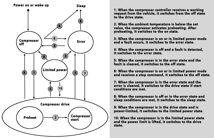
Figure 2 Schematic diagram of compressor state transition
Electric variable-speed compressors play a crucial role in EVs, directly influencing the performance of the vehicle's AC system. This article analyzes and studies the control principles, software protection strategies, and vehicle interaction aspects of electric compressors, providing references for the design, development, and after-sales maintenance of e-compressors. With the continuous development of EV technology, control strategies for electric compressors will also improve to adapt to more complex application scenarios.